Cinelifters carrying a RED KOMODO or similar cinema-camera setup place much greater demands on a battery than standard 5-inch FPV drones. Carrying a RED KOMODO camera increases the cinelifter's takeoff weight and power demand. During hard climbs, rapid acceleration, or recovery maneuvers, the motors draw more current and place greater stress on the battery.
If the battery and power system cannot maintain voltage under these loads, voltage sag occurs. While some sag is normal in any LiPo battery, excessive sag can reduce thrust consistency, shorten flight time, increase battery temperature, and reduce the safety margin during demanding shots. For this reason, identifying where voltage is being lost is more useful than simply choosing a battery with the highest C-rating.

Executive Summary: What Causes Cinelifter Voltage Sag?
The simplest electrical relationship is:
Vsag = I × Rtotal
where I is the current drawn by the aircraft and Rtotal is the effective
resistance of the battery and the complete high-current path.
Voltage sag becomes more severe when either current demand or circuit resistance increases. On a cinelifter, the main contributors include battery-cell internal resistance, cell condition and temperature, battery leads, connectors, solder joints, parallel harnesses, and power-distribution wiring. Reducing voltage sag requires a complete-system approach: use low-resistance and well-matched cells, select a battery with sufficient real discharge performance, minimize resistance in the wiring and connectors, managebattery temperature, and validate the system under realistic flight loads.
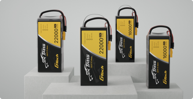
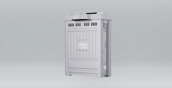
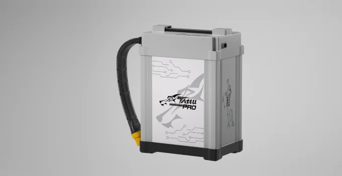
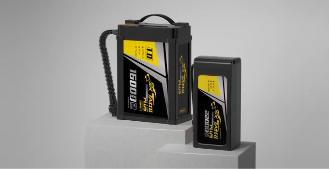
For some large cinelifters, moving from 6S to a properly designed 8S powersystem can also reduce current for the same power demand. Tattu currentlypositions its 8S LiPo platform for larger FPV airframes, including cinematic andheavy-load applications where additional electrical headroom is required.
Why Voltage Sag Matters More on Heavy-Payload Cinelifters
A battery may look healthy before takeoff and still experience a significant voltage drop during a demanding maneuver. For example, the pilot may seenormal pack voltage in hover, but during a hard climb or rapid acceleration, the voltage suddenly falls and then partially recovers as soon as throttle is reduced.
This is typical load-induced voltage sag.
Reduced Thrust Reserve
Motor speed and available thrust depend partly on the voltage reaching the
ESCs and motors. When battery voltage falls substantially under load, the
propulsion system loses part of its available electrical headroom.
On a lightweight freestyle quad, this may simply feel like reduced punch. On a cinelifter carrying an expensive cinema payload, the consequences are more important. Reduced thrust reserve can affect rapid climbs, recovery from descending shots, acceleration after turns, and other maneuvers where the pilot needs immediate power.
For cinematic FPV, predictable response is often more important than
maximum theoretical output. A drone that behaves differently at the beginning
and end of every flight is harder to operate consistently on set.
Power-System Brownout Risk
VVoltage sag does not always cause a flight controller or video system to reset. These components usually receive power through voltage regulators. However, a severe voltage drop can still cause problems if the regulator's input voltage falls below its operating range. However, if the input voltage falls outside a regulator's usablerange, or if the BEC, wiring, or connector is already operating near its limits,severe voltage drop can contribute to unstable electronics.
Possible symptoms include receiver resets, video interruption, telemetry loss,or peripheral-device instability. When this occurs, diagnose the complete
power architecture instead of assuming the battery alone is responsible.
Higher Battery Stress
High current combined with elevated internal resistance generates
additional heat. The approximate resistive heating relationship is:
Ploss = I²R
Current therefore has a particularly strong effect on heat generation. Repeated high-current operation at low state of charge can also make sag
progressively more noticeable. Aging, excessive heat, cell imbalance, unsuitable
storage, and repeated deep discharge can all increase the effective resistance
of a LiPo battery over time.
What Causes Excessive Voltage Sag on a Cinelifter?
Voltage sag should be analyzed as a complete electrical-path problem. A useful model is:
Vloaded = Vopen − I × Rtotal
The real battery response is more complex because electrochemical
polarization, temperature, state of charge, and transient behavior also matter,
but this equation provides a useful engineering starting point.
Suppose a cinelifter draws 180 A during acceleration and the combined
effective resistance of the power path is 12 mΩ:
Vsag = 180 × 0.012 = 2.16 V
Note: This 12 mΩ value represents the assumed total effective resistance of the circuit, not the internal resistance of an individual cell.
Reducing the resistance to 8 mΩ would reduce the calculated resistive drop
to approximately 1.44 V under the same current. That difference can materially affect the voltage available to the
propulsion system.

High Cell Internal Resistance
Cell internal resistance, commonly shortened to IR, is one of the most
important factors. Lower IR generally means less voltage loss and less resistive heating at
the same current. Just as importantly, cells within the same battery should be
well matched. A single cell with significantly higher resistance can become the limiting
cell during a heavy-current maneuver.
However, IR should not be treated as a universal number that can be
compared between every charger and battery. Temperature, SOC, cell capacity, test frequency, equipment, contact
resistance, and measurement procedure all affect the reading. If an OEM uses a
requirement such as "<1.5 mΩ per cell," the measurement conditions should
also be defined.
For pilots, tracking changes with the same charger and procedure is often
more useful than comparing absolute IR readings from different equipment.
C-Rating Does Not Tell the Whole Story
The familiar formula is:
Theoretical current = Capacity (Ah) × C-rating
But this calculation does not tell you what voltage the battery will
maintain at that current, how hot it will become, or how long it can sustain the
load.
This distinction is particularly important for cinelifters. Tattu's FPV battery testing also shows why printed C-rating alone should
not be used as a universal performance ranking: loaded-voltage behavior, usable
energy, temperature, and resistance all need to be considered when comparing
high-performance FPV batteries.
For a heavy cinema drone, evaluate the actual discharge curve rather than
selecting a pack solely because its label shows a larger C number.
Wiring and Connector Resistance
Battery cells are only one part of the power path. Resistance can also come from long battery leads, undersized wire,
connector contacts, parallel adapters, solder joints, crimps, and
power-distribution boards.
At high current, even a small additional resistance becomes
significant. A connector or cable that performs well on a 5-inch FPV drone should
therefore not automatically be used on a substantially larger X8 cinelifter.
Single Battery vs. Dual Parallel Batteries for Cinelifters
Dual-battery systems are common on larger cinematic FPV builds, but they
should be evaluated electrically rather than simply assuming that "two batteries
are safer."
| Factor | Single Pack | Two Matched Packs in Parallel |
| Battery equivalent resistance | R | Approximately R/2 in the ideal case |
| Current per pack | Full system current | Approximately half the system current |
| Capacity | One pack capacity | Approximately twice the capacity |
| Battery mass | Lower | Higher |
| Wiring complexity | Simpler | More connectors and wiring |
| CG flexibility | More limited | Packs can be positioned separately |
| Current sharing | Not applicable | Depends on battery and harness matching |
| Failure behavior | Simpler to analyze | Parallel connection does not automatically provide true redundancy |
For two identical batteries with resistance R, the ideal equivalent battery
resistance in parallel is approximately:
Rparallel = R / 2
If the aircraft draws 160 A, two well-matched parallel batteries would
ideally provide approximately 80 A each. This reduces the load placed on each pack and can reduce battery-related
voltage sag.
However, the ideal result assumes similar batteries and symmetrical
electrical paths. The packs should be closely matched in voltage, state of charge,
temperature, age, internal resistance, connector condition, and wiring
resistance. Connecting batteries with materially different voltages can create
large equalization currents before the aircraft even takes off.
Dual parallel batteries can therefore be highly effective, but only when
the aircraft is designed around them. A sufficiently capable single pack may still be the better solution when
minimizing battery mass, connector count, wiring complexity, or installation
volume is the priority.
Does an 8S Battery Reduce Voltage Sag Compared With 6S?
For large cinelifters, battery voltage is another important design
variable. Electrical power can be approximated as:
P = V × I
For the same required power, increasing voltage reduces the required
current. Consider an idealized 3,000 W propulsion demand.
At the nominal voltage of a 6S LiPo:
3,000 W ÷ 22.2 V ≈ 135 A
At the nominal voltage of an 8S LiPo:
3,000 W ÷ 29.6 V ≈ 101 A
At the same theoretical power, an 8S system draws approximately 25% less current than a 6S system. This can reduce resistive losses in cables and connectors, improving power delivery efficiency.
However, an 8S battery does not automatically produce less voltage sag. Actual voltage drop also depends on cell count, internal resistance, battery capacity, and temperature. Pilots should compare loaded voltage and battery performance under similar operating conditions before choosing between 6S and 8S.
The lower current demand at a given power level is one reason 8S systems are increasingly relevant to larger cinematic FPV platforms. Tattu's current 8S lineup is specifically positioned for large
propeller setups, high continuous power demand, cinematic FPV, and heavy-load
FPV applications.
However, moving from 6S to 8S is not a battery-only upgrade. Motors, motor KV, ESC voltage rating, capacitors, flight-controller power
input, BECs, wiring, and tuning must all be compatible with the higher
voltage.
If the aircraft was engineered around 6S, installing an 8S battery without
verifying the entire powertrain can damage components.
For a more detailed comparison, see Tattu's guide to 6S vs. 8S LiPo
batteries for FPV drones.
How to Reduce Cinelifter Voltage Sag
Step 1: Select Low-Resistance, Well-Matched Batteries
Start with battery quality rather than capacity alone. For demanding cinelifter applications, compare loaded voltage, internal
resistance consistency, temperature rise, cell balance, usable capacity, and
performance after repeated cycles.
A good pack should not only deliver high peak power when new. It should
maintain predictable performance throughout its useful service life.

Step 2: Match Battery Capacity to Real Current Demand
Increasing capacity can reduce the electrical stress placed on the cells,
but larger batteries also add aircraft mass. More capacity is therefore not automatically better.
Determine the aircraft's takeoff weight, hover current, normal filming
current, transient peak current, required flight time, and acceptable battery
mass. The best battery is the one that satisfies the power requirement without
adding unnecessary weight.
Step 3: Use Appropriate Wire and Connectors
High-current cinelifters often require heavier wiring than conventional FPV
drones. 8 AWG or 10 AWG silicone wire may be appropriate for some high-power
builds, while others may require different conductor sizes. Selection should be
based on actual current, cable length, temperature rise, allowable voltage drop,
insulation rating, and installation conditions.
The same applies to connectors. Higher-current anti-spark connectors such as XT90-S or AS150-type systems
may be appropriate on large builds, but connector selection should be validated
against the real operating current rather than chosen by drone size alone.
Keep high-current cables as short as practical and pay close attention to
solder joints, crimps, and connector condition.
Step 4: Manage Battery Temperature
Cold LiPo batteries generally show greater effective resistance and poorer
high-current performance. For cold-weather or high-altitude shooting, keep batteries within the
manufacturer's recommended operating-temperature range before flight. Controlled
battery warming and insulated transport solutions can help when appropriate.
Do not use uncontrolled heat, and never attempt to heat a damaged or
swollen LiPo battery.
Step 5: Test With the Real Payload
Do not qualify a cinema drone using an unloaded aircraft and then assume it
will behave the same way after installing the camera system.
Test with representative takeoff weight and reproduce demanding maneuvers
such as climbs, acceleration, rapid recovery, and sustained high-throttle
operation. Blackbox logs can then be used to compare current demand and battery
voltage.
The most useful question is not "How many amps did the drone pull?"
It is:
How much voltage did the battery maintain while delivering that
current?
Frequently Asked Questions About Cinelifter Voltage Sag
Q1. How do I test battery voltage sag accurately?
Record battery voltage and current simultaneously during a repeatable
maneuver using calibrated onboard sensors and Blackbox logging.
A useful approximation is:
Dynamic resistance ≈ ΔV / ΔI
Perform the test at similar battery temperature, SOC, payload, and flight
conditions when comparing packs.
Smart-charger IR measurements can also help track battery aging when the
same charger and procedure are used consistently. For engineering validation,
dedicated battery cyclers or programmable loads provide more repeatable
measurements.
Q2. Can a battery with excessive voltage sag be repaired?
It depends on the source of resistance.
A damaged connector, poor solder joint, undersized wire, or cold battery
may be corrected.
Permanent increases in cell resistance caused by aging or degradation
generally cannot be reversed through charging.
A swollen, mechanically damaged, or abnormally hot LiPo battery should not
be used for critical cinelifter flights.
Q3. Can Betaflight VBat Sag Compensation eliminate voltage sag?
No.
VBat Sag Compensation adjusts motor output as battery voltage changes to
help maintain more consistent throttle and PID behavior throughout the flight.
It does not reduce the physical resistance of the battery or restore voltage
already lost in the electrical system. Betaflight's current documentation
describes the feature as a way to maintain more consistent motor response across
the battery-voltage range.
TPA is also a PID-tuning function rather than a battery-sag solution.
If peak power demand must be reduced, motor or throttle output limits can
be considered, but only after verifying that sufficient thrust reserve remains
for the fully loaded aircraft.
Q4. Why do parallel batteries usually sag less?
Two closely matched packs connected in parallel divide the current between
them and reduce the effective battery resistance.
In the ideal case, two equal-resistance packs provide approximately half
the equivalent battery resistance of a single pack.
Real performance depends on cell matching, wiring, connector resistance,
temperature, and SOC.
Q5. How can I prevent premature battery sag and swelling?
Avoid unnecessarily long periods at full charge, follow the manufacturer's
recommended storage-voltage procedure, prevent excessive heat and deep
discharge, and inspect packs regularly.
For professional use, record changes in internal resistance, temperature,
cell balance, and flight behavior.
A battery that begins sagging significantly more under the same load should
be removed from critical-flight service before the problem becomes severe.
Conclusion: Treat Voltage Sag as a System-Level Constraint
Voltage sag on a heavy-payload cinelifter is rarely caused by a single component. It is the result of the interaction between battery internal resistance, current demand, wiring resistance, connector losses, temperature, state of charge, and the propulsion system itself.
For that reason, troubleshooting should begin with measurement rather than assumptions. Record voltage and current under repeatable flight conditions, compare packs at similar temperature and state of charge, inspect the complete high-current path, and pay attention to how the system behaves during the maneuvers that create the highest load.
If excessive sag appears only at high current, the priority is to determine where the additional resistance or electrical stress is coming from. That may mean replacing an aging battery, reducing connector or wiring losses, improving current sharing in a parallel setup, or reconsidering whether the existing voltage platform is appropriate for the required power level.
For professional cinelifter operation, the goal is not to eliminate every measurable voltage drop. Some sag is unavoidable in any real battery system. The more practical objective is to keep loaded voltage, temperature rise, and cell behavior within predictable limits throughout the shot.
A well-designed power system should therefore be judged by repeatability: similar voltage behavior, similar thermal performance, and similar throttle response from one flight to the next. That consistency is ultimately more valuable than a single peak-current figure or an advertised C-rating.








 Blog
Blog
 Blog
Blog
 Blog
Blog


